
Introduction
Here is some powerful processing that was the foundation for solving a business requirement in at least 4 client sites over the years.
I call it the Frontage Problem.
Precis
Linear referencing can be used to compute points at set distances from the start of the line, with left or right of that line.
The Frontage processing described in this article does a number of things:
- Finds the polygon line that shares a boundary with the road/street resevre;
- Finds both the corners this boundary shares with itself, or
- Computes a centre point in the middle of the selected boundary
- Optionally computes a bearing/distance (0-360 degrees) or a clockface “bearing” (0h 0min – 11hr 11:30min) from this boundary to any object nearby.
For example one might want to compute either bearing and distance or clockface references from the middle of the land parcel’s boundary that adjoins the street reserve to an object, such as a telecommunications pit in that street reserve.
Like all things spatial, some pictures will show this more clearly than a few words.

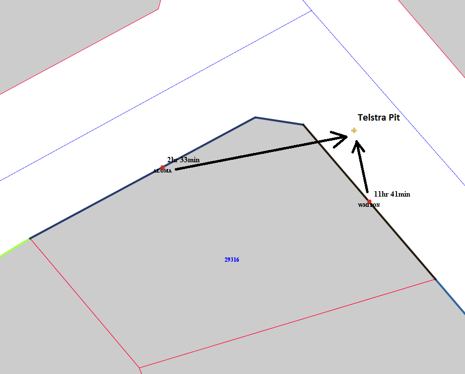
In the above example, the reference from the centre of the boundary of land parcel 128780 to the object in the street reserve is 6hours 2 minutes for 37.34 meters (see later).
Business Problem: Field Survey
The business problem that frontage processing implements is where field staff need to identify, service and examine objects in the street which may be difficult to identify. For example an old service pit which is flush to the ground and may even have been covered over by soil and grass. The original position is known but hard to find. Using traditional linear referencing may not inefficient if the starting measure for a road is hundreds of meters away. Finding the middle of a frontage boundary in the city may be relatively easy where a shop front is synonymous with the boundary; and in the country (where I live), a fenced property boundary is easy to identify.
OK, now I can hear you all saying, but if you know the location (X,Y/Latitude,Longitude), why not just use GPS navigation. To which I reply: if you have an accurate GPS field device (not a smart phone), and the satellite constellation for the time the field visit occurs is excellent, then Yes, take it and use it. But remember, the readout from the GPS probably is not accurate enough to locate the object (certainly in the Southern Hemisphere, the GPS satellite constellation is far less optimal than the Northern Hemisphere).
Let’s not argue the toss as it is a “both / and” argument.
Use all methods available: take a map, an orthophoto (if available), a GPS, and the ClockFace Direction/Bearing and distance, as the cost to travel to the location is normally greater than the pre-field survey (and you don’t want to have to visit the site more than once)!
Implementation
The implementation is one based entirely on database based objects and processing.
Database Types
The solution uses database PL/SQL Object types.
Here are the main frontage ones …..
Create Or replace Type T_GeomRow AS Object (
   gid      number,
   name     varchar2(1000),
   geometry mdsys.sdo_geometry
);
/
show errors

Create Or Replace Type T_Geometries
    As Table Of T_GeomRow;
/
show errors

create or replace TYPE T_ClockFace IS OBJECT (
  clockface varchar2(20),
  distance  number(8,2),
  centroid  mdsys.sdo_geometry,
  vector    mdsys.sdo_geometry
);
/
show errors
And a package of stored procedures deployed inside the database (data tier).
(Data tier solutions are flexible as they can be consumed by any web service or client that can connect to the database and call the stored procedure.)
A packaged function and its overload, looks like this:
CREATE PACKAGE FRONTAGE
AUTHID CURRENT_USER
AS

...

   /* ***********************************************************************
    * ******************** Main Function ************************************
    * ***********************************************************************
    **/
   FUNCTION Clockface(P_CAD_ID      IN varchar2,
                      P_STREET_NAME IN varchar2,
                      P_STREET_OBJ  IN MDSYS.SDO_GEOMETRY,
                      p_dec_places  IN INTEGER DEFAULT 2,
                      p_tolerance   IN NUMBER  DEFAULT 0.005)
     RETURN t_clockface Deterministic;

   /* *******************************************
    * ************* Overloads *******************
    * *******************************************
    **/
   FUNCTION Clockface(P_CAD_ID       IN varchar2,
                      P_STREET_NAME  IN varchar2,
                      P_STREET_OBJ_X IN NUMBER,
                      P_STREET_OBJ_Y IN NUMBER,
                      P_SRID         IN NUMBER DEFAULT 3112,
                      p_dec_places   IN INTEGER DEFAULT 2,
                      p_tolerance    IN NUMBER  DEFAULT 0.005)
     RETURN t_clockface Deterministic;
...
END FRONTAGE;
/

<h3>Example</h3>

Here is an example how to call the function to generate a reference to a telecommunications pit in the road reserve at my house.

[code type="sql"]
SELECT FRONTAGE.clockface(
          P_CAD_ID      => '128780',
          P_STREET_NAME => 'Cliff View Drive',
          P_STREET_OBJ_X => cogo.dms2dd('147 12'' 14.83"E'),
          P_STREET_OBJ_Y => cogo.dms2dd('43 00'' 49.76"S'),
          P_SRID         => 4283,
          p_dec_places   => 6,
          p_tolerance    => 0.05)
         AS direction
  FROM dual;

CLOCKFACE_DIRECTION
---------------------------------------------------------------------------------------------------
SPDBA.T_CLOCKFACE(
 /*clockface*/ '16hr 2min',
 /*distance */ 37.34,
 /*centroid */ SDO_GEOMETRY(2001,4283,SDO_POINT_TYPE(147.204125,-43.013822,NULL),NULL,NULL),
 /*vector   */ SDO_GEOMETRY(2002,4283,NULL,
                            SDO_ELEM_INFO_ARRAY(1,2,1),
                            SDO_ORDINATE_ARRAY(147.204125,-43.013822,147.20411944,-43.01415833))
)
Inputs
What are the inputs to this problem?
In all cases the base spatial data were two tables containing:
- Land Parcel Polygon objects (as individual objects, not in a topological structure); In this situation all polygons that share boundaries eg 127907 and 128780 in the image above duplicate the shared boundary as it is a segment within the polygon exterior ring. The land parcel polygon data should be of high quality so that shared boundary segments are truly shared (the data released in the PSMA’s CADLite product is of such quality). Additionally, those two segments have different direction which needs to be handled in the processing (see my article on flipping vectors in SQL Server Spatial – available for Oracle as well). In a topological data structure (Oracle SDO_TOPO or PostGIS Topology) that shared boundary would exist as a single linestring.
- Named Street Centreline linestring objects. In the implementations no street reserve polygon exists.
The point object defining the object in the street reserve may come from multiple sources. It could be a user click on a map, an existing asset eg telecommunications pit, a lamp post, etc.
The user inputs are:
- The land parcel reference eg id = 128780
- The name (or id) of the street that contains the object eg “Cliff View Drive” (id = 62544)
Approach
The approach my solution takes is as follows:
1. Select the desired land parcel;
2. Determine its frontage boundary linestring(s);
3. If more than one boundary linestring is returned, query the street centreline data and select the nearest boundary;
4. Compute the middle (midpoint) of the street frontage linestring;
5. Compute and return the bearing/clockface and distance to object.
Algorithm
The process for determining the frontage of a parcel is:
1. Select all neighbouring land parcels to the desired parcel;
2. Segmentize the polygons into 2 point linestrings;
3. Execute segment flipping and keep only those segments for which there is only one of them. This removes all shared boundaries.
4. For each frontage segment select the nearest road centreline that has the desired name and is within a maximum distance. For example, many roads in Australia are placed in land parcels that are 1 Chain wide or 20.115 m. This can help discard single segments that are a part of a boundary with a lake.
5. Then join the selected segments to create a single linestring that represents the land parcel’s street frontage. This involves some extra processing that is not described here.
6. Once a linestring has been formed, generate a centroid in the middle using Linear Reference processing. One customer wanted the centroid to be in the middle of the frontage but 5m inside the land parcel.
7. Once the centroid is created a Bearing or ClockFace Direction and distance to a supplied point can be calculated.
Utility Function
To compute the clockface value, function is needed that will convert a whole circle bearing from 0 – 360 to its clockface equivalent.
CREATE PACKAGE FRONTAGE
AUTHID CURRENT_USER
AS

...

   FUNCTION DD2TIME(p_dDecDeg IN NUMBER,
                    p_24_hour IN INTEGER DEFAULT 0)
     RETURN VarChar2
   IS
     v_dDecDeg NUMBER := Round((p_dDecDeg/360)*12,2);
     v_iDeg    INTEGER;
     v_iMin    INTEGER;
   BEGIN
     v_iDeg := TRUNC(v_dDecDeg);
     v_iMin := (v_dDecDeg - v_iDeg) * 60;
     RETURN TO_CHAR(CASE WHEN NVL(p_24_hour,0)=0
                         THEN v_iDeg
                         ELSE 12 + v_iDeg
                     END
                   ) ||
                   'Hr ' ||
                   TO_CHAR(v_iMin) ||
                   'min';
   END DD2TIME;

...

END FRONTAGE;
/
Example of Use of Utility Function
The following example uses DD2TIME and a generate_series object (yes it could use LEVEL and CONNECT BY), to create all Clockface entries every 30 minutes from 0 hr to 12 hr.
I call this “Rocking around the Clock”.
 SELECT FRONTAGE .DD2TIME(t.COLUMN_VALUE) AS clockface
   FROM TABLE(generate_series(0,360,15)) t

CLOCKFACE
---------
0Hr 0min
0Hr 30min
1Hr 0min
1Hr 30min
2Hr 0min
2Hr 30min
3Hr 0min
3Hr 30min
4Hr 0min
4Hr 30min
5Hr 0min
5Hr 30min
6Hr 0min
6Hr 30min
7Hr 0min
7Hr 30min
8Hr 0min
8Hr 30min
9Hr 0min
9Hr 30min
10Hr 0min
10Hr 30min
11Hr 0min
11Hr 30min
0Hr 0min

 18 ROWS selected
Creating Frontages for a whole Subdivision.
An example of a block of land parcels that have had ALL their frontages defined in one process is shown in the following image.

There is a lot of processing involved so speed can be an issue, but this is a question of scale. That is, how many land parcels to process at any one time. At one site the speed to process a single land parcel and produce a result was considered acceptable for dynamic access.
This type of processing has been used in real systems.
The code is only available as an Oracle PL/SQL package.
It could be converted to SQL Server Spatial TSQL or PostgreSQL / PostGIS pgPlSQL by negotiation.
I hope it is of interest to someone.